


Join Six Sigma Microelectronics at CMSE 2026! Visit our booth and attend Minerva Cruz’s presentation on BGA Reballing for mission-critical applications.
As part of the nation’s effort to sustain the microelectronics manufacturing capability necessary for national and economic security, and in support of Executive Order 14017, America’s Supply Chains, the Department of Defense recently entered a $10 million agreement with Six Sigma utilizing Defense Production Act (DPA) Title III authorities. Six Sigma will increase the capacity of both its copper solder column manufacturing and column attach processes to enable the production of high-reliability Column Grid Array components (such as Field Programmable Gate Arrays and Application Specific Integrated Circuits) for military and aerospace applications. The project will run 51-months and be performed at its facility in Milpitas, California. “This investment ensures critical DoD military and space programs operating in extreme thermal and vibration environments are available to meet the needs of American strategic interests,” said Dr. Taylor-Kale, ASD (IBP). “It exemplifies the Department’s commitment to ensuring the resilience and integrity of our nation’s critical supply chains.” About the Department of Defense’s Office of the Assistant Secretary of Defense for Industrial Base Policy Industrial Base Policy is the principal advisor to the Under Secretary of Defense for Acquisition and Sustainment (USD(A&S)) for developing Department of Defense policies for the maintenance of the United States defense industrial base (DIB), executing small business programs and policy, and conduction geo-economic analysis and assessments. The office also provides the USD(A&S) with recommendations on budget matters related to the DIB, anticipates and closes gaps in manufacturing capabilities for defense systems, and assesses impacts related to mergers, acquisition, and divestitures. IBP monitors and assesses the impact of foreign investments in the United States and executes authorities under sections 2501 and 2505 U.S.C. Title 10. See DoD Press Release

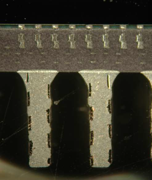
This study focuses on identifying the residues found on the surface of high temperature co-fired ceramic packages after prolonged exposure to moisture. Read the PDF